Unable to get the rifling I wanted from other sources, I designed and built my own sine-bar rifling machine.
A rack and pinion are affixed to a diagonal track (adjustable) and a linear carriage. The carriage houses the pinion gear and is rotated by the rack as they move up and down the I-beam. Since the rack can move in and out of the carriage, due to the angle of its track, the rifling cutter can be rotated to give a precise and repeatable twist rate.
The following pictures demonstrate the machine and rifling head as used for 2 of the Lukens barrels. I’m presently making the rifling head for the Girardoni rifles.

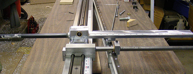
Here is the end view of the machine. The main frame is a 4″x4″ Al I-beam. The diagonal to the right is the sine-bar and is Al channel. These elements have linear guides attached for smooth travel. The Al clamp and rod closest to us is an end stop, adjustable for barrel length and twist. The next assembly is the carriage containing the rack and pinion. At the far end resides the barrel vise and indexer.

Here are the guts of the carriage. From left to right:
Carriage housing with linear guides at bottom, needle bearings pressed into bore and rack support extending to the right.
Pinion gear with torrington thrust bearing. The gear has a 1″ diametrical pitch, therefore 3.1416 ” of rack travel gives 1 revolution of the cutter.
Bronze bushing to seat gear and adjust endplay.
The rack is at the bottom of the picture.

Here are the guides and tracks of the carriage. Note the rack passing through the carriage and the diagonal sine bar in the background.

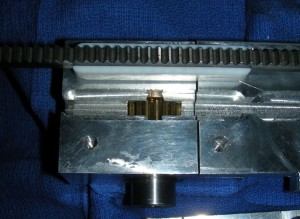
Underside of carriage with pinion gear installed. The groove for the rack is visible as is the uninstalled rack above.

Here is the rack and its teflon guide assembled on the gear. The bottom 0f the carriage is ready to be attached. The central hole in the carriage base has a set screw to adjust clearance of the rack and pinion gear.

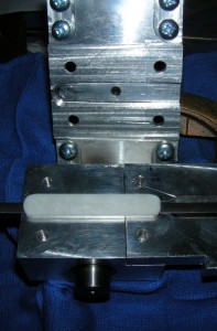
Here is the carriage assembled without the rack to show the relation of the gear, track and teflon rack guide.

Top of assembled carriage. Tapes are glued to the track and rack guide to allow setting the twist rate. Here we are at 40″ of twist. A length of grey PVC pipe estends to the left to protect the extended rack. Below, the end stop is set for the barrel length.

At the other end of the machine is the barrel vise. Two pillow blocks support a length of 1.5″ tubing. At each end, four screws secure the barrel concentrically in the tube. To the right is the indexer to select nunber and position of the grooves to be cut.

The indexer has three rows of holes (7, 12 and 15 positions) to allow any where from 1 to 7, 12 or 15 grooves to be cut in a barrel. The holes are selected by the black springloaded plunger which can be clamped inline with the requisite row.
Since the machine is primarily aluminum, it is easily moved and stored. Here I am lifting it ~50 lbs.
The disassembled riling head. The tube is above into which is inserted the cutter and wedge. A tapered pin retains and acts as a pivot for the cutter. The o-ring acts as a spring to drop the cutter when the wedge is retracted. The adjusting rod extends to the right and allows the cutter to be raised and lowered.
Closeup of the cutter and wedge.
Cutter raised and lowered.
Here are some balls showing the rifling (.32 cal – Lukens). Three shots @ 25 yards.


